OMM 350UNI
OMM 350UNI
3 ½ digit MULTIFUNCTION INSTRUMENT
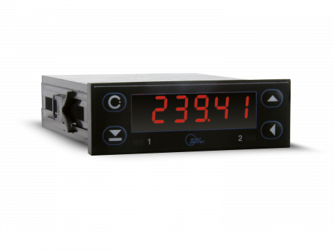
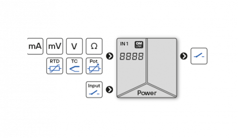
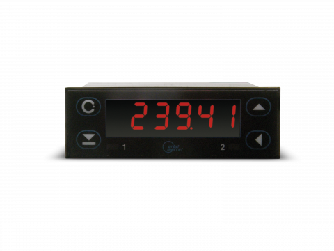
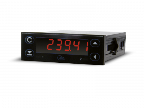
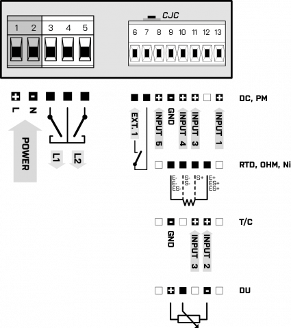
The OMM 350 model series are small 3 ½ digit panel programmable instruments designed for maximum usefulness and user comfort while maintaining their fair price. Type OMM 350UNI is a multifunction instrument with the possibility of configuration for 8 different input options, easily configurable in the instrument menu. The instrument is based on a single-chip microcontroller and an A/D converter, which ensure good accuracy, stability and easy operation of the instrument.
-
3 ½ digit programmable projection
-
multifunction input UNI (DC, PM, RTD, T/C, DU)
-
digital filters, tare, linearization
-
size of DIN 72 x 24 mm
-
power supply 10…30 VDC/24 VAC
Input
DC
Range
menu selectable
±20 mV
> 10 MOhm
Input 4
±60 mV
> 10 MOhm
Input 3
±1 000 mV
1,25 MOhm
Input 1
PM
Range
menu selectable
0…20 mA
< 200 mV
Input 5
4…20 mA
< 200 mV
Input 5
0…2 V
10 MOhm
Input 4
0…5 V
1,25 MOhm
Input 1
0…10 V
1,25 MOhm
Input 1
OHM
Range
menu selectable
0…100 Ohm
0…300 Ohm
0…1,5 kOhm
0…3 kOhm
0…30 kOhm
0…100 Ohm
0…300 Ohm
0…1,5 kOhm
0…3 kOhm
0…30 kOhm
Connection
2, 3 or 4-wire
RTD
Type
menu selectable
EU > 100/500/1 000 Ohm s 3 850 ppm/°C
-50°…450°C
RU > 50 Ohm s 3 910 ppm/°C
-200°…1 100°C
RU > 100 Ohm s 3 910 ppm/°C
-200°…450°C
US > 100 Ohm s 3 920 ppm/°C
-50°…450°C
Connection
2, 3 or 4-wire
Ni
Type
menu selectable
Ni 1 000/10 000 s 5 000 ppm/°C
-50°…250°C
Ni 1 000/10 000 s 6 180 ppm/°C
-50°…250°C
Connection
2, 3 or 4-wire
Cu
Type
menu selectable
Cu 50/100 with 4 260 ppm/°C
-50°…200°C
Cu 50/100 with 4 280 ppm/°C
-200°…200°C
Connection
2-, 3-, or 4-wire
T/C
Type
selecmenu selectable
J (Fe-CuNi)
Input 3
-200°…900°C
K (NiCr-Ni)
Input 3
-200°…1 300°C
T (Cu-CuNi)
Input 4
-200°…400°C
E (NiCr-CuNi)
Input 3
-200°…690°C
B (PtRh30-PtRh6)
Input 4
300°…1 820°C
S (PtRh10-Pt)
Input 4
-50°…1 760°C
R (Pt13Rh-Pt)
Input 4
-50°…1 740°C
N (Omegalloy)
Input 3
-200°…1 300°C
L (Fe-CuNi)
Input 3
-200°…900°C
DU
Range
Configuration is performed in two steps:
| 1. | setting numerical value for the beginning and end of the potentiometer range |
| 2. | slider position calibration for the beginning and end of the potentiometer runway |
Potentiometer power supply
2,5 VDC/6 mA, potentiometer resistance > 500 Ohm
External inputs
Number
1 input, on contact
Functions
| OFF | No function |
| HOLD | Stopping measurement (option: Display - Analog output - Limits) |
| TARA | Tare activation |
Projection
Display range
-99999…999999,single-coloured 7-segment LED
Display height
9,1 mm
Display colour
red, green
Decimal point
menu adjustable - fixed or floating
Display brightness
menu adjustable
Settings
Control
The device is controlled and set by four buttons on the front panel
Menu
| LIGHT | contains only items necessary for basic device settings with password access |
| PROFI | Full device settings with password access |
| USER | User menu of any item, selected from LIGHT/PROFI. Access without password. |
Optional functions
| ZAKAZ | button has no function |
| TARE | Activating function Tare |
| NUL. TA. | Tare reset |
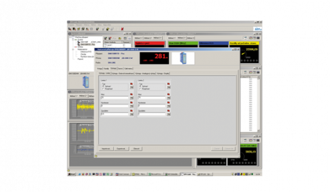
OM Link
Company communication interface for operation, setting and update of device firmware
OM Link program is also designed for visualization and filing of meas. values from more instruments
OM Link program is also designed for visualization and filing of meas. values from more instruments
Instrument accuracy and functionality
Temperature coefficient
50 ppm/°C
Accuracy
±0,2 % of range + 1 digit
±0,3 % of range + 1 digit (T/C)
±0,3 % of range + 1 digit (T/C)
Accuracy of cold junction measurement
±1,5°C
Rate
0,5/1,2/2,5/5/10 measur./s
Overload capacity
2x; 10x (t < 30 ms)
Resolution (RTD, T/C)
1°C, 0,1°C
Wire compensation (RTD, OHM)
< 30 Ohm
Cold junction compensation
adjustable -20°…99°C, automatic
Linearization
linear interpolation in 25 points (only via OM Link)
Digital filters
| exponential mean | from 2…100 measurements |
| rounding | setting projection step for display |
Functions
| Tare | designed to reset display on non-zero input signal |
Watch-dog
reset after 500 ms
Calibration
at 25°C and 40 % r.h.
Comparators
Type
Digital, menu adjustable, contact connect. < 50 ms
Mode
| Hysteresis | switch. point, hysteresis band "Mez ± 1/2 Hys." and time (0 ... 99.9 s) determ. switching delay |
Output
1x bistable relay (48 VAC/30 VDC, 3A)
2x bistable relay (48 VAC/30 VDC, 3A)
1x open collector (30 VDC/100 mA)
2x open collector (30 VDC/100 mA)
2x bistable relay (48 VAC/30 VDC, 3A)
1x open collector (30 VDC/100 mA)
2x open collector (30 VDC/100 mA)
Power supply
Power supply
10…30 VDC/24 VAC, ±10 %, PF > 0,4, I < 45 A/1 ms, isolated
Current draw
< 2,1 W/2,2 VA
Operating conditions
Connection
connector terminal board, cable section < 1,5/2,5 mm2
Stabilization period
within 15 minutes after switch on
Operating temperature
-20°…60°C
Storage temperature
-20°…80°C
Protection class
IP42 (front panel only)
El. safety
EN 61010-1, A2
Dielectric strength
2,5 kVAC within 1 min. between pow. supply and input
4 kVAC within 1 min. between input and relay output
4 kVAC within 1 min. between input and relay output
Insulation resistance
for polution degree II, measuring cat. III.
| power supply | 300 V (ZI)* |
| input, output | 300 V (ZI), 150 V (Di)* |
EMC
EN 61326-1
Seismic capacity
IEC 980: 1993, par.6
Mechanical properties
Material
Noryl GFN2 SE1, non-inflammable UL 94 V-I
Dimensions
72 x 24 x 106 mm (w x h x d)
Panel cutout
68 x 21,5 mm (w x h)
Datasheets
User manuals
| File name | File type | Version | Language | Download |
|---|---|---|---|---|
| Operating instructions OMM350 |
PDF
|
2007.1.1 | en | Download |
| Návod OMM350 |
PDF
|
2016.1.1 | cs | Download |
Certificates
| File name | File type | Version | Language | Download |
|---|---|---|---|---|
|
Certificate EU_Declaration_OMM350_650
Certifikát EU_Prohlaseni_OMM350_650
|
PDF
|
2022 |
|
Download |
|
Certificate Declaration_17050_OMM350_650
Certifikát Prohlaseni_17050_OMM350_650
|
PDF
|
2022 |
|
Download |
|
Certificate Seismic_test_OMM350UNI
Certifikát Seizmicka_zkouzka_OMM350UNI
|
PDF
|
2008 |
|
Download |
Firmware
| File name | File type | Version | Language | Download |
|---|---|---|---|---|
|
OMM350UNI 61-002 Pt Ni1000
OMM350UNI 61-002 Ni10000
OMM350UNI 61-002 Pt100
OMM350UNI 61-002 Pt500
|
HEX
|
2007 |
|
Download |
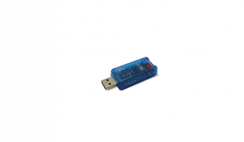
ISOLATED TRANSDUCER • USB < > OM INSTRUMENTS
Small compact transducer OM LINK USB with cable ensures safe and comfortable galvanically isolated connection between your computer and ORBIT MERRET instruments.
